Testing Facility

Testing of microwave absorber

Testing of microwave absorber

Introduction of Testing Standard

IEEE-1128:

IEEE Recommended Practice for Radio-Frequency (RF) Absorber Evaluation in the Range of 30MHz to 5GHz

THE PURPOSE IS:

1. To recommend realistic and repeatable criteria as well as test methods

2. To characterize the absorption properties of typical anechoic chamber linings applied to a metallic surface.

3. To cover the frequency range of 30 MHz to 5 GHz and beyond

RF Absorber Reflectivity Measurement Procedures

As per IEEE-1128 There are four techniques.

1. The arch method, uses a transmit and a receive antenna that are mounted on a circular arch that is in a plane perpendicular to the RF absorber surface.

2. The second method uses a time-domain approach. The RF absorber is mounted on any wall or on the floor of an enclosed area.

3. The third method mounts the RF absorber array or tile at the end of a waveguide with a large cross-section and an appropriate length.

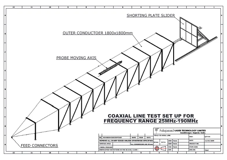
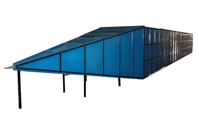
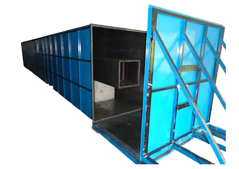
4. The fourth method is based in the same idea as the third method, except that a coaxial line with a large cross section and an appropriate length is used instead of the waveguide.
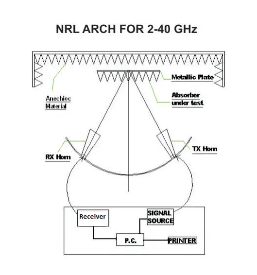
NRL Arch Method

This is extremely simple and intuitive measurement method.

First, the reflection of a metal plate at the center of the arch is measured.

Next, the sample to be evaluated is placed on top of the metallic plate, and its reflection is measured.

The ratio of the sample reflection to the metal plate reflection is the reflection coefficient.

NRL ARCH of 1800MM radius to test absorbers from 2GHz to 40GHz with horn pairs covering the entire frequency region.


Limitation of NRL Arch Method

It usually used above 2.0 GHz. Secondary parameters include

1. Edge diffraction effects from the sample

2. Direct coupling between the measurement antennas,

3. Extraneous reflections from the environment,

4. The fact that the effective plane of reflection of the sample is offset from the metal plate’s plane of reflection by virtue of the sample thickness.

Limitation of NRL Arch Method

FrequencySample SizeAccuracy in MeasurementReflection Coefficient
Lowest10λ x 10λ±1dB20 dB
Lowest10λ x 10λ±3dB30 dB
Lowest10λ x 10λ±10dB40 dB

The enclosed-waveguide measurement procedure (250MHz -1GHz)

The enclosed-waveguide measurement procedure, also known as the flared-waveguide measurement procedure, uses a length of waveguide with a cross-section the size of the standard RF absorber tile or of a small array of them.

The waveguide is excited at one end with a probe that is designed to excite only the TE10 mode. The other end is closed by the RF absorber under test as shown in Figure.


Enclosed waveguide method proceeds as follows:

The frequency band of the waveguide is selected for use on a vector network analyzer and its S-parameter test set. Within that band, 201 sample points are chosen for measurement.

One-port calibration for S11 is performed on the network analyzer (accounting for directivity, frequency response, and port mismatch of the system).

Enclosed waveguide method proceeds as follows:

The network analyzer is connected to the waveguide via coaxial cable to the feed end of the guide.

A 0.6 m × 0.6 m (2 ft × 2 ft) piece of RF absorber is then placed in the guide. See Figure.

The time-domain gating function on the analyzer is turned on, and the gate is set around the area where the sample under test is placed in the guide. This is an important step because it eliminates from the measurement undesired reflections caused by imperfections in the waveguide and the interconnecting cables.

The reflection coefficient is then measured directly from S11.

Testing Facility for 700MHz to 1GHz

Wave Guide Test Set-up with Non linear Dolph-Chebyshev taper for Frequency 700MHz-1050MHz.


Testing Facility for 250MHz to 500MHz

Wave Guide Test Set-up with Non linear Dolph-Chebyshev taper for Frequency 250MHz-500MHz


Low-frequency coaxial reflectometer measurement procedure(25MHz to 190MHz)

A variation of the enclosed waveguide test method uses a special coaxial air-filled line. This is commonly referred to as the low-frequency coaxial reflectometer (LCR) method.

A coaxial line, supporting a TEM wave, simulates the free-space wave incident on RF absorbers and does not have a low-frequency cutoff.

Design : Square inner conductor with a square outer conductor that is three times the size of the inner conductor. This configuration will take eight 0.6 m × 0.6 m (2 ft × 2 ft) RF absorber tiles to conduct a reflectivity measurement.

Test procedure

Turn on the vector network analyzer, and allow it at least 15 min to warm up.

Set the start and stop frequencies of the vector network analyzer.

select the S11 measurement option.

When possible, the test start frequency should be chosen so that it is below the lowest frequency to be measured by at least 10% of the measurement frequency range.

Perform a full one-port S11 calibration at the cable connector that connects to the LCR.

Install the metallic shorting plate to measure the reflection coefficient of the shorted line, with time-domain gating to discriminate the reflection from characteristic impedance mismatch. This trace should be recorded in the computer as the reflectivity reference.

Load eight pieces of full-size absorber to cover the shorting plate, as shown in Figure

Measure the reflection coefficient again with the time-domain gating. The time gate settings of the two measurements with the metallic plate and the absorber may or may not be the same.

The ratio of the reflection coefficients from the two measurements is computed and recorded as the absorber reflectivity, in dB.

Testing Facility

Coaxial line Test set-up of 1800x1800mm outer & 600x600mm inner conductor and length is 16m for the frequency range 25MHz to 190MHz.

Testing Facility for 25MHz to 190MHz


Coaxial line Test set-up

Coaxial line Test set-up

//